I've managed to source more parts now for the RC projects, including:
- Set of 4x Ansmann 95mm Shocks
- A pair of HPI Saturn 35T Motor
- An HPI Firebolt 15T Motor
- Lots of Tamiya ESC (104 model) - for existing and new vehicles
I'm now just short of linkages/suspension arms for the truck, which I'm not finding easy at best. Think I might have to machine them, or find something I can re-engineer...
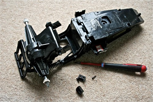
This afternoon I started stripping down the RC buggy I managed to buy for peanuts at the local car boot sale last week. My objective is to fit a new ESC, new Rx and motor if needed, and generally cleanup/improve the thing.
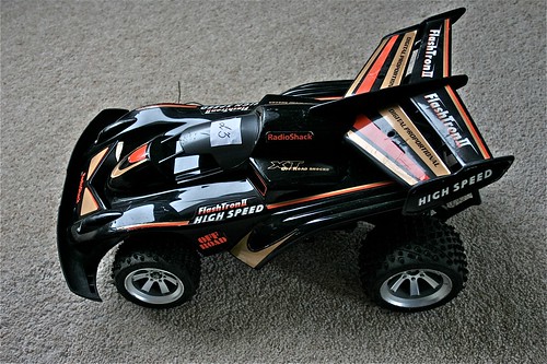 |
| Radioshack Flashtron II |
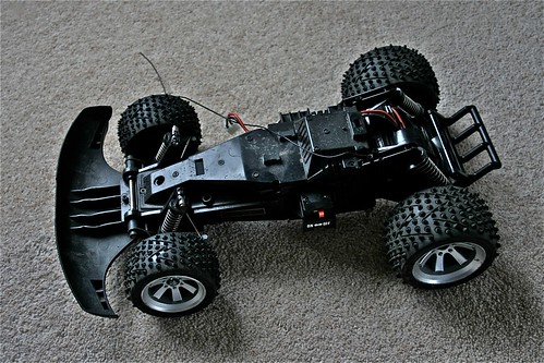 |
| Three screws later, and sans-shell. |
It was surprisingly easy to break down, as most is held together with screws, with some hinge pins in places (explained later on). The wheels use regular lock nuts to hold them in place, so a metric pit tool was all that I needed for them. Quite often I've seen wheels compression fitted, crimped or even held on with grub screws. It was refreshing to see keyed axles too - it opens up the potential future uses for the buggy and makes it easier to service and rebuild.
 |
| Ready to start stripping down... |
Taking the electronics cover off, I was shocked at the gunky mess inside. A combination of sand and gel the PCB has been coated in, has resulted in a complete mess. The buggy is incredibly clean on the outside, so I really wasn't expecting this, but since the old electronics are going, it's no real concern for me - just a bit of extra work cleaning it up (ie a soapy bath for it).
 |
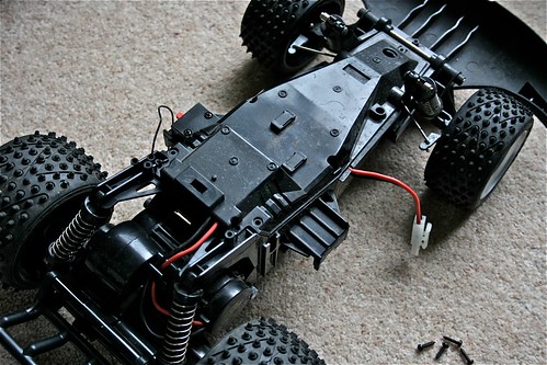
| The main bathtub and electronics bay protected by a single cover. |
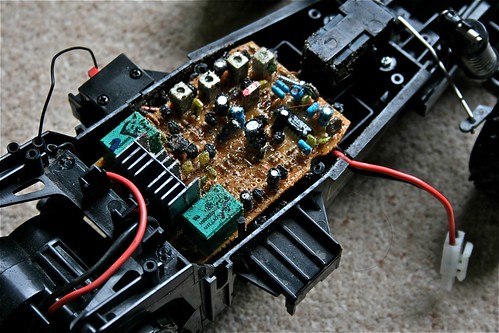 |
| Sand and gunk (probably seawater in the mix too) ≠ happy electronics. |
The electronics bay is packed solid with the old controller, so it will be straight forward fitting a 2.4Ghz Rx and a Tamiya 101 model ESC. There are plenty of air vents (enough for the bay to have been filled with sand in the past), so no real worries of overheating, and there are existing cable entry points, so no hacking required.
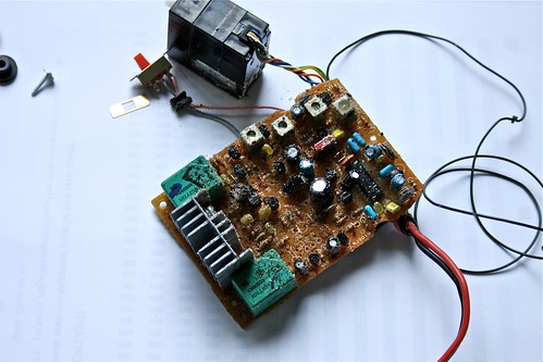 |
| Easily replaceable; the original electronics and servo. |
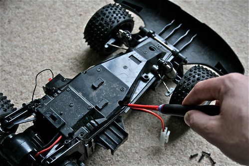
The motor has been soldered directly to the main board, along with the battery cable. The latter I'll chop off and keep, as those connectors are expensive (unnecessarily so). The motor will need a suitable connector for the new ESC - I'm not sure whether to fit something industrial, or just hack a solution. Failing that, I might just use a stock Tamiya motor, and do away with worrying about it.
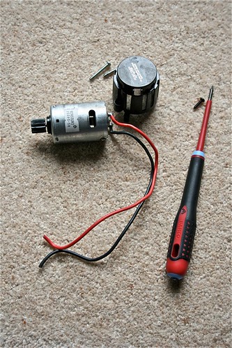 |
| Stock Radioshack 540 motor. |
The old servo will also be going, replaced with a stock Acoms servo, and some spare Tamiya servo collars/horns. Rather bizarrely, the buggy features a standard servo mount with standard server horns - no custom plastic or weird case-less servos you normally find in RTR vehicles. It's a deep servo, so I may need to pack out the replacement servo (or completely bypass the mount, and do things differently). It'll probably need something higher-torque, but for now it'll do - first things first, I just want this to run on new electronics.
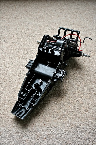 |
| Bathtub chassis with rear-end, sans-everything else. |
I tried to open the gearbox, but found the rear-end is connected by a pin with caps that appear to be expansion fitted - so will require the pin to be cut to open the gearbox housing. I won't bother for now, unless the gearbox plays up badly, as I would need to replace the pin with something similarly tight fitting either bolted in place, or held by circlips.
 |
| It can be stripped further, but the hinge pin makes it pointless to do so. |
The front end came off easily, and since the suspension is also held together with similar pins, I'm not going to bother breaking down any more - just clean up and grease what I can. The bathtub chassis is nice and robust, and not cracked or damaged - there are plenty of scratches on the bottom, and on the bumper, but frankly there'll be more there soon :)
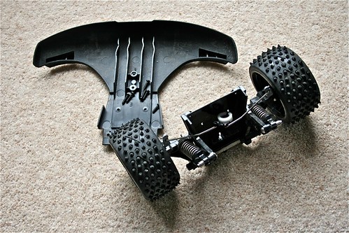 |
| Front-end with servo horn. |
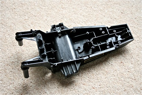 |
| The final stripped bathtub, ready for a wash. |
All-in-all, this looks to be in good running order, and with the upgraded electronics will be a nice little buggy to play with. In Part 2, I'll cover the reassembly, with some pictures of it running.
Finally, I'll leave you with the battery cover (well, a really clever clamp mechanism for holding a regular Ni-Cd/Ni-Mh 7.2V pack in place), sporting it's Radioshack part number.
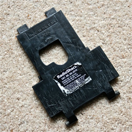 |
| Radioshack Flashtron II 60-4215 |
wow i have 1 of those but mine is working! i wonder if mine is like that or not(dirty in the inside). i just picked mine up a few days ago and i was wondering if i can make it faster? and my battery will be plugged in for 16 hours and i can only play w/ it for about a 1/2 an hour, do you think its my battery or is yours like that too? how long does yours last? do you have any suggestions?
ReplyDeleteHi Nate,
DeleteIf you check out part 2, you'll see the rebuild of the buggy. I replaced all of the electronics, installed a new motor and replaced the steering servo.
From the sounds of it, you've got a fairly regular NiCd battery pack, coupled with a slow charger. Depending on the battery pack specifications, you may be able to use a fast charger to reduce the charge time from 14-16 hours to 45-180 min.
In terms of runtime, your mileage may vary, but expect 15-30 mins. Bare in mind you're pulling a massive load off the battery pack (you'll find it's quite warm after you run it). Do a search for more info on batteries, there's lots of good resources out there.
I use a fairly intelligent Ansmann charge station, coupled with high-grade battery packs, give me pretty short charge times and good runtimes.
Hey, I also have one of these with the blue decaling instead of the bronze. Ive had it since new and was just thinking about it the other day. I am missing the remote as well as the battery. Do you think a hobby shop would have a universal remote with a tunable frequency that would work with this?
ReplyDeleteHi Jason,
DeleteFor analogue remotes, you'll need to know the exact frequency of the receiver to match a new remote to - there's no guarantee they've even mapped the same signals to F/R L/R, so the controls could be mixed up. With better remotes, there would be a replaceable crystal, letting you pick the frequencies you're racing with (you buy them in a pair, one for the Rx and one for the Tx) - you're still going to have issue with the controls, as even the best remotes only let you flip axis not interchange them. In most probabilities, if you bought a new remote it would come with a receiver, so you may as well just replace the electronics, which will be an easier job.
On a better note, the battery is a standard Ni-Cd/Mh 6-cell profile with a Tamiya connector. They're readily available (have a look on eBay) and quite cheap these days.
Thanks for the reply Mccoy. Well the good news is i had no problem getting a battery (as you said i wouldnt) and i now have an AM remote with an interchangeable crystal, as for the controls being mixed up im not to concerned about that for now, but i have come across a new problem. The crystal in my car says it 26.74 MHz and i cant seem to find a crystal for the transmitter lower than 26.995 is there a possibility of finding this crystal?(possibly if i knew who made this car for radio shack) or do you think i would have any luck trying to soldier a new crystal into the existing circuit board of the car?(keeping in mind I do realize replacing everything with more modern stuff is most likely inevitable, but i need to try to do it the hard way first lol)
ReplyDeleteJust had a quick search and it seems that the crystal you need is a 27.195 receiver (type 5)...
DeleteTo quote "26.740 + .455 = 27.195 - seems correct for a single conversion receiver with 455kHz IF" followed by "That's a difference of 455 KHz, which is the most common intermediate frequency used by single-conversion receivers.
"After passing through the receiver's front end, the incoming frequency of 27.195 MHz is combined with the 26.740 MHz signal from the crystal by a mixer to produce the intermediate frequency of 455 KHz through the process of heterodyning. The 455 KHz signal is then isolated by a bandpass filter and processed further."
Hope that helps. Personally, I'd just go for a replacement receiver and ESC as you have no idea how the actual transmissions are mapped to functions. You can pickup a new ESC and Receiver for probably the same cost of sourcing crystals that'll fit.
An intriguing discussion may be worth comment. I’m sure you should write much more about this topic, may well be described as a taboo subject but generally folks are too little to chat on such topics. An additional. Cheers Blog RC crawler
ReplyDelete#RCCar #RCCars #BestRcCar. RC Car - 10 Best RC Cars to buy 2019 (which RC vehicle is perfect) ... (LiPo Battery Required), 1:8 Scale (Blue) Amazo long range fpv car
ReplyDeleteYour insight on this topic is truly enlightening. tableau online course
ReplyDelete