Main Controls
I've gotten most of the push buttons and physical controls, and have devised numerous solutions for the main quadrant controls now.
The first solution I devised, is to take some Telemec' joysticks, and rip them apart, building a custom aluminium framework to house them, and attaching a suitable mechanism to actuate a potentiometer. The second, is to not bother with quadrant controls...
As I've found, there are virtually no manufactures of them around, and those I've found are ludicrously expensive (or are an import job). In the end, the controls I thought would be the hardest to source (rotary hand wheels/levers) are actually proving to be the more easier.
So, for this first version, the brake will be a hand wheel with knob, and the throttle will be a rotary lever. I'm still awaiting the lever, but have already snagged a couple of the hand wheels. No picture at the moment, but will add one later.
Enclosure
The new enclosure arrived - I'm somewhat limited to space and initially to the kind of enclosure, so for the first panel, I'm tied to the dimensions based upon the largest pre-manufactured enclosure I could find.
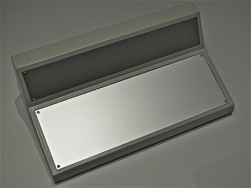 |
| Boss Enclosure |
The enclosure should be deep enough for most of the components - where possible I'll tier/stack the Arduino boards on the back of some of the interface elements, and the others will be placed at the rear/back (the deepest part). Some of the Telemecanique controls are deep, so I'll have to cheat with positioning if I hit problems.
The layout of both panels will be done in CAD; I'll outline each component, and include it's cut-out, allowing me to shuffle around. I'll digitally precision cut a prototype panel out of card in our engineering lab, so I'll have something I can mount the controls to, and sit into the enclosure to check it works, and feels right.
Once I'm satisfied, I'll use an accurate overlay to mark the aluminium and to cut it. I don't have access to a laser or CNC cutter so I'll have to do it carefully with a bench drill - most of it is circular so no big issues. For square cuts, I'll have to ensure that the control has a bezel that will hide any imperfections.
I've got a large stock of anodised aluminium extruded profiles, so I can easily build up and build down for some of the controls - perhaps making some look modular or segregated. Anything I make will bolt together - I'll rivet if needed, and I'll avoid welding the aluminium if at all possible.
Even though the enclosure is a beautiful shade of fresh-vomit-beige, I'll hopefully be spraying it to a bluish-grey that's common for modern train cabs - I'll need to play around with shades to get it right, and I'll avoid two-toning the plastic case. The aluminium probably needs painting as well, again that'll be a nice bluish-grey, though I may make it a dark grey for better contrast with the labels and pilot lamps.
All of the legends and labelling will be printed/precision-cut polyester, with a polycarbonate laminate - it's what's used on control panels, and should look great. Not sure whether to completely cover the aluminium, or just do it around each control. The CAD will help immensely in getting the artwork accurately shaped and cut.
Controls
As mentioned in the previous post, there's going to be a bit of work involved in integrating the panel with a DCC system. It's not going to be quite as easy as focusing on controls first and then programming afterward - I'll need to know how the programming will work, in order to figure how the controls can be implemented (and which are needed or should be avoided).
I would hope/expect at the least to have the following controls:
- Throttle
- Brake (with simulated deceleration/proportional braking)
- Emergency Brake (emergency stop controls, bypassing the deceleration configuration)
- Direction (forward/off/reverse)
- Horn A (high tone)
- Horn B (low tone)
On top of those controls the following could be included:
- Parking Brake (on/off with pilot indicator)
- Pantograph (up/down with pilot indicator)
With it being a DCC controller, there's a lot of benefits in having a full compliment of controls that can be mapped to the function keys, and have them labelled in accordance to what they normally are (and coloured/laid out appropriately). Then again, there's finite space, so some will be tactile, and others will have to be soft-controls, and accessed through JMRI or a DCC-orientated keypad (like a PS/2 keypad etc).
 |
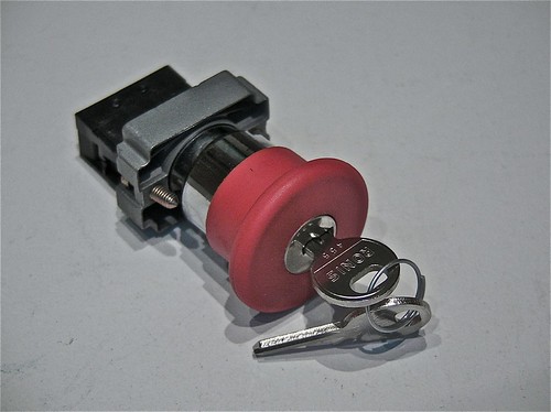
| Telemec' Joystick & Rotary Key Switch |
 |
| Telemec' Mushroom Key Button |
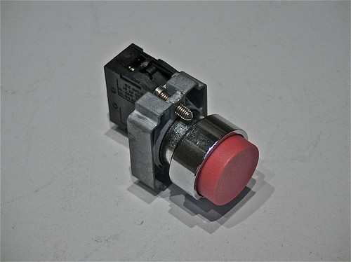 |
| Telemec' Push Button |
Information Panel & Feedback
Part of the panel is to control a train, and part is to control the DCC functionality (such as consisting, selecting a train etc). Looking at modern train cabs, many feature glass-panel displays for diagnostics, train overviews (i.e. showing the rolling stock, consisting etc) and schedule information. In our case, we have JMRI, which will be offering a big chunk of this information - and in the same way as the real systems will need to have some form of tactile interface (touch screen or keypad), we'll need the same.
I don't want the DCC aspect to be obvious - it's whether I include a tactile interface on the panel, use a touch screen or rely upon an external keypad. Whichever, I need info from JMRI, and I need info for the DCC controller. And I need to control them both.
There's quite a bit of feedback for the panel to display - indicators, LCD's and needle gauges. I'm inclined to avoid needle gauges, and use multi-line LCD displays in their place.
The indicators could include:
- AWS
- Alarm
- Overload/Trip
With displays/guages including:
- DCC Config
- Speed
- JMRI Info
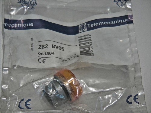 |
| Telemec' Amber Pilot Lamp (sans-bulb holder) |
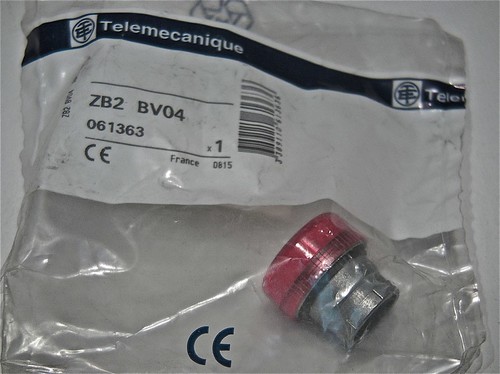 |
| Telemec' Red Pilot Lamp (sans-bulb holder) |
Programming & Function Mapping
An important part of designing the panel, is ensuring there are enough input controls to cover the most important functions, and mapping them correctly. This requires a bit of deep research, figuring out what standards there are, what I can actually control and how they're controlled. Simply, if a horn is generally a specific Fx number, then I need to know which it is, so I can map it to the correct button, conversely some functionality that should be on the control panel might not be controllable - it might need to be programmed instead or is hardwired, such as lighting etc.
As it seems that I'm headed towards an information display as part of the overall panel, then most of the functionality will be mapped out in a GUI form (mimicking a real-life HMI) - this should also serve as a means to select trains and interact with the LCB as needed.
Bigger decisions are with the underlying electronics and interfacing. I've spent a good few weeks researching the electronics, both prototype and scale, my conclusions of which are far too long for this post, so I'll ramble along on that subject later. I've got quite a few design considerations to make, and to decide on the buses and technologies that I'll build the panel and future layouts upon.
Resources
My first port of call will be MERG, the Model Electronic Railway Group, a membership-based society in the UK that focuses solely on the electronics aspect of model trains - there's some really interesting projects I'll probably cover in the future, including position locations using RFID and servo point control.
A great resource is OpenDCC, a German-based OpenSource project, that consists of hardware and software - including great guidance on implementing and programming DCC. The English translations are a little ropey in places, or missing altogether, but nonetheless this is the best resource I've seen (and seems to have the best technical understanding).
The JMRI project is of course an excellent source of information, though a quick Google search turns up some great blogs and presentations on JMRI.
Another great project that I recently found, Rocrail, offers an attractive alternative to JMRI, and something worth looking at.
Another useful resource is the NMRA, the National Model Rail Association - though US based, is pretty much the norm for most model rail standards, so will be reference for any integration with DCC.
Next Steps...
As you can see, I'm still trying to figure things out, and am planning/designing on the fly. I started writing this post weeks ago, re-writing every time something new came up, or a problem was solved, or a new problem was found. I'm getting closer, I think...
