Over the last few weeks, I've become obsessed with vinyl, and screen-print artwork. My aim is to make vinyl artwork with the feel of screen printing, but the textures and durability of vinyl. Why hang a piece of art, when you can turn a wall or any surface you have into a work of art? (Rhetorical question, I'll have you find).
Anyhow, I've been screwing about in the studio with vinyl cutters and thermal presses, with the hopes of creating something great. I'm hoping to work with a couple of awesome illustrators to produce some unique pieces of artwork, so stay tuned for more info.
In the meanwhile, if you're interested in my vinyl services, including; cutting (vinyl, metallic films, stencil film etc) and thermal printing, then get in touch with me: jon(at) followed by shotbymccoy.com. We can cut, mark and print most materials, so if in doubt, feel free to ask!
I'm trying to figure a way of combining my photography with my vinyl, to create a bastardised format... I have some crazy ideas in mind, I'll endeavour to post some as I get shooting.
Ta-tah for now...
Saturday, 25 June 2011
Saturday, 11 June 2011
RC Buggy Project Part 2
Having been watching the F1 trials in Canada for most of the day (interspersed with watching Japanese new channel NHK), I'm lusting after a glistening workshop, complete with gloss white tool cabinets, gloss white workspaces and a torque wrench. I'm hoping my new lab-slash-studio will look as cool when it's finalised - it's got white walls, ceiling and a grey floor, so we're on the way!
Anyway, in this final part of the project, I'll be rebuilding the buggy with new electronics, and getting it ready for it's test drive.
I've been waiting for nearly a month now for some of the parts (in general, not just for this), and a good few weeks for others. I had to steal a few parts from an existing car (motor and speed controller), but that'll have replacement ones and a new Rx as soon as the parts arrive anyway.
I decided to save time and effort by using a stock Tamiya 27T motor, complete with bullet connectors and the Tamiya 101 ESC it was attached to, off of my Tamiya Enzo Ferrari... I've also used a new 2.4Ghz Rx instead, not just for reliability but for it's miniature size (they're a good 75% smaller than analogue Rx).
Inventory:
The first step was to wash the parts, minus the gearbox, which got a good wipe down instead. I ended up submerging and washing the other parts (all plastic minus the front-end) which made it a lot easier to get the sand and gunge out.
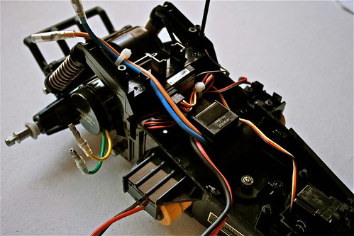
Once dried and ready to re-assemble, I tried dry-fitting the electronics into the main bathtub as best I could, along with the servo. With the lid on, the servo fitted and with a bit of shuffling, the electronics did as well. Interestingly there was a slot perfectly in line with the top flange of the servo (with a recess and raised guides for the bottom flange) and even a space for the servo cable.
Once everything was in place (with cable ties), I tackled the servo mount, which ended up being a saddle by virtue of using long enough screws and allowing the bracket to bend over the servo a little. There's a little pressure from the bracket against the top lid, but nothing significant. Long term, it may be better to carve a chunk of the plastic from the top of the servo slot to give the bracket some clearance, but for now it'll run perfectly without doing so.
The servo sits without any movement and moves freely without obstruction, so all in all the servo replacement has been straightforward. I couldn't use the original servo horn, given the tooth shape, but having to only replace one component has to be pretty good!
In rebuilding the back-end, I used the original push-on pinion gear and the Tamiya 27T motor stolen from my Ferrari. There wasn't much to do with the back-end, apart from routing the cables (which will be zip tied to the upper suspension arm), and reattaching to the main bathtub chassis.
I test drove the buggy in the driveway, and all seems good. Took a hell of a lot of trimming to get the steering and throttle correctly balanced - the steering servo needed reversing as well. I'm enjoying the FlySky controller, I like the setup and the ability to tweak all of the settings whilst the vehicle is moving. Though still getting used to the controls, and the "End" button being the "Enter" button, and the "Enter" button being the "Select" button.
When Ms R. is back, we'll take the buggy to the park, and film it in action. Until then, I'll start getting to grips with the chassis design for the new truck.
Anyway, in this final part of the project, I'll be rebuilding the buggy with new electronics, and getting it ready for it's test drive.
I've been waiting for nearly a month now for some of the parts (in general, not just for this), and a good few weeks for others. I had to steal a few parts from an existing car (motor and speed controller), but that'll have replacement ones and a new Rx as soon as the parts arrive anyway.
I decided to save time and effort by using a stock Tamiya 27T motor, complete with bullet connectors and the Tamiya 101 ESC it was attached to, off of my Tamiya Enzo Ferrari... I've also used a new 2.4Ghz Rx instead, not just for reliability but for it's miniature size (they're a good 75% smaller than analogue Rx).
Inventory:
- Motor: Tamiya 540 27T (any 540 approx 27T will do)
- ESC: Tamiya TEU101-BK
- Servo: Acoms AS17
- Radio Tx: FlySky GT3B
- Radio Rx: FlySky GR3C
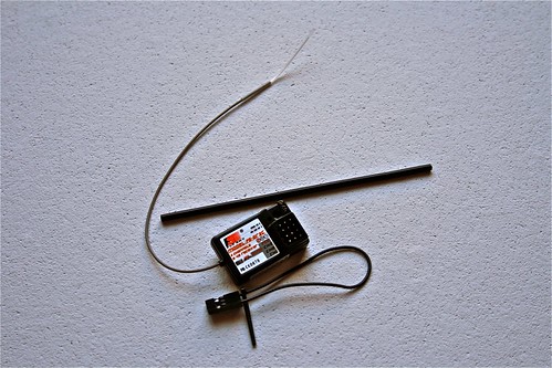 |
| FlySky 2.4Ghz Receiver |
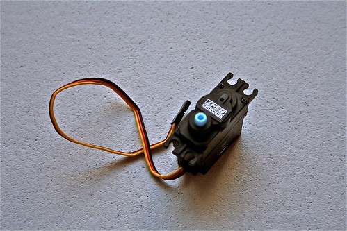 |
| Stock Acoms Servo |
The first step was to wash the parts, minus the gearbox, which got a good wipe down instead. I ended up submerging and washing the other parts (all plastic minus the front-end) which made it a lot easier to get the sand and gunge out.
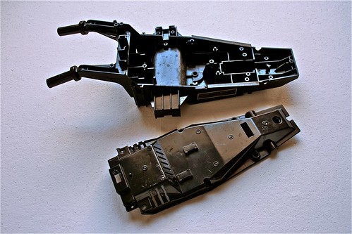 |
| Clean parts ready for re-assembly. |
Once dried and ready to re-assemble, I tried dry-fitting the electronics into the main bathtub as best I could, along with the servo. With the lid on, the servo fitted and with a bit of shuffling, the electronics did as well. Interestingly there was a slot perfectly in line with the top flange of the servo (with a recess and raised guides for the bottom flange) and even a space for the servo cable.
 |
| Dry-fitting components. |
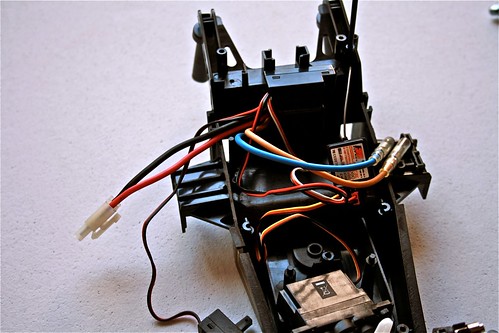
Once everything was in place (with cable ties), I tackled the servo mount, which ended up being a saddle by virtue of using long enough screws and allowing the bracket to bend over the servo a little. There's a little pressure from the bracket against the top lid, but nothing significant. Long term, it may be better to carve a chunk of the plastic from the top of the servo slot to give the bracket some clearance, but for now it'll run perfectly without doing so.
 |
| Cable tied and neatly organised. |
The servo sits without any movement and moves freely without obstruction, so all in all the servo replacement has been straightforward. I couldn't use the original servo horn, given the tooth shape, but having to only replace one component has to be pretty good!
 |
| Servo mounted with original servo saddle. |
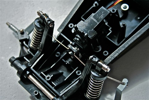
In rebuilding the back-end, I used the original push-on pinion gear and the Tamiya 27T motor stolen from my Ferrari. There wasn't much to do with the back-end, apart from routing the cables (which will be zip tied to the upper suspension arm), and reattaching to the main bathtub chassis.
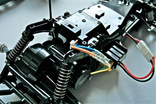 |
| Back-end with new Tamiya 27T motor. |
 |
| Assembled and ready to go, sans-shell... |
 |
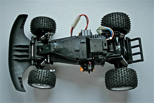
| Ready to go... |
I test drove the buggy in the driveway, and all seems good. Took a hell of a lot of trimming to get the steering and throttle correctly balanced - the steering servo needed reversing as well. I'm enjoying the FlySky controller, I like the setup and the ability to tweak all of the settings whilst the vehicle is moving. Though still getting used to the controls, and the "End" button being the "Enter" button, and the "Enter" button being the "Select" button.
When Ms R. is back, we'll take the buggy to the park, and film it in action. Until then, I'll start getting to grips with the chassis design for the new truck.
Thursday, 9 June 2011
The RC Truck Part 1: Design and Parts
In lieu of a decent name at present for the rock-crawler slash 4x4 slash thing with wheels, I'm going to call it the "Truck".
I can see this turning into a long series of posts, to get enough detail and ramblings in for the whole design and construction process.
In this first post, I'll cover most of the design logic, and a lot of the parts being used. By no means will this be a finalized design prior assembly, nor a parts inventory, but should give others dumb enough to want to build an RC vehicle like this, sufficient pointers to get something under way.
Chassis
The design for the chassis is where the whole idea came from - to build a basic structure using aluminium extruded profiles and with conventional fixtures and fittings.
I've got a lot of ideas for chassis, and given how much aluminium I've got, I'll probably try a few (I may even consider using quick-release hardware to enable the axles to be moved between chassis). Dictated by the axles, the scale and general structure will be built to accommodate the positioning of the suspension and linkage mount points. As the battery and electronics are discrete enough to be fitted anywhere there's space; the axles are the most critical thing to secure before construction.
I may consider a payload on the vehicle, so it may be necessary to tweak the design accordingly, to create a bit of useful space. I'm thinking mainly electronics so not a massive weight.
Axles & Drive Trains
I can see only two ways of approaching a project like this - hack or buy existing axles. Falling short of designing a gear box, axles and housing, I thing the best solution is to either hack existing drive train components or to buy whole drive trains. The former still leaves a lot of issues, as to building a housing and getting the steering, diffs, axles and gearboxes mashed together. The latter is a lot easier, as you can either rip the units of existing used vehicles (eBay etc), or buy the drive trains as spares. The trouble comes in ensuring the chassis is somewhat similar in proportions to the original vehicles, at least in terms of linking the suspension and the four pairs of linkages.
From an early stage I opted for Motor-on-Axle rather than using a drive shaft to a centrally mounted gearbox, for a start it makes each drive train a single unit that just needs power, it increases the range of motion, lowers the centre of gravity and reduces the number of moving parts liable to screw up.
I couldn't find anything used in the time frame I set myself, so I sourced a pair of Gmade drive trains (sans-motor, pinion gear and servo). The beauty of these is that they're reversible, allowing for a simpler mirrored chassis design and also allowing for front and rear steering.
The drive trains do have diffs, and from what I understand, they're not lockable on this, falling short of gluing the diff, or filling with diff lock grease. Can't have everything.
Suspension & Linkages
This area is giving me the most grief.
Hardware wise, I think I'll source either spare parts from HPI or Axial cars, or try to source anodized aluminium hex nuts/bolts - not an easy task either way.
I've sourced Ansmann 95mm shocks for front and back, and I'm on the lookout for linkages. I'm planning to use two pairs of links for each axle; forming a "W" shape. The suspension will be almost vertical so there'll be plenty of movement and sufficient rigidity.
Edit #1: I've sourced a set of Axial XR-10 linkages and chassis mounts, so hopefully it'll all come together.
Edit #2: Having now received the axles, it looks like my search for linkages was in vein, as they've got a complete set with them, plus lots of extra bits as well. And a really dumb error, I assumed the XR-10 was 1/8th scale for some reason, but it's 1/10th. The linkages should be okay though, as the they have the right mechanical specs - though I might not need them if the Gmade ones are good enough.
Motors & Electronics
As mentioned, both axles will be powered by 35 turn HPI Saturn motors. They're quite general purpose, so it'll have a bit more speed than regular rock crawlers, with a loss in capability on the rockier terrain. They're easy to replace at any time, so I can always put 55 turn for some heavy rock crawling.
I'll be using another 3-channel 2.4Ghz Rx, so I'll have an extra channel to play with (perhaps to enable/disable rear steering etc). For cost and simplicity I'll start with a single Tamiya ESC (104), Y-linked to the motors, allowing for parallel control of both motors. I may find that a bad solution, especially if one axle gets jammed, and the other motor gets fried - but I'll need to play around with the safety and overloads of the ESC, and just be careful in general.
The front axle will have steering, with option of unlocking the rear and putting steering on that too. I might gear down the servo on the rear to reduce the steering effect, that I'm not sure of at present. Initially I'll build with a stock Acoms servo, but I will install higher-torque ones as needed - I can see this being an issue very quickly.
Wheels & Tyres
I've luckily managed to source a set of Axial SCX-10 rims and tyres, so all should be sorted on that front. That makes for a nice short section.
Body Shell
I'm undecided what I want it to look like... It can go any direction at this stage! I do like the look of the Axial XR-10, so I might take that approach, at the same time a Land Rover 110 would be cool. And also making it look like a military robot has it's charms too (think carbon fibre looking, works well with all of the aluminium). I'll sketch a few ideas out, and see where it takes me.
With the 1/8th axle scale, it's going to be a little harder to find a suitable shell, without this looking like a monster truck (not a bad thing, but not the intention). I'm also inclined to fit a lot of surveillance equipment, so a more ruggedized shell will probably be called upon! I'm probably going to rename it something pointless, like the "All Terrain Surveillance Drone" or ATSD if that's the case.
For now, I think that rounds of most of the "design", and explains most of the parts I'm using and the reasoning behind it. In the next few parts, I'll cover the build-out of each component and some interesting little tidbits along the way too.
I'm off to start cutting aluminium and bolting crap together.
Wednesday, 1 June 2011
RC Buggy Project Part 1
I've managed to source more parts now for the RC projects, including:
This afternoon I started stripping down the RC buggy I managed to buy for peanuts at the local car boot sale last week. My objective is to fit a new ESC, new Rx and motor if needed, and generally cleanup/improve the thing.
It was surprisingly easy to break down, as most is held together with screws, with some hinge pins in places (explained later on). The wheels use regular lock nuts to hold them in place, so a metric pit tool was all that I needed for them. Quite often I've seen wheels compression fitted, crimped or even held on with grub screws. It was refreshing to see keyed axles too - it opens up the potential future uses for the buggy and makes it easier to service and rebuild.
Taking the electronics cover off, I was shocked at the gunky mess inside. A combination of sand and gel the PCB has been coated in, has resulted in a complete mess. The buggy is incredibly clean on the outside, so I really wasn't expecting this, but since the old electronics are going, it's no real concern for me - just a bit of extra work cleaning it up (ie a soapy bath for it).
The electronics bay is packed solid with the old controller, so it will be straight forward fitting a 2.4Ghz Rx and a Tamiya 101 model ESC. There are plenty of air vents (enough for the bay to have been filled with sand in the past), so no real worries of overheating, and there are existing cable entry points, so no hacking required.
The motor has been soldered directly to the main board, along with the battery cable. The latter I'll chop off and keep, as those connectors are expensive (unnecessarily so). The motor will need a suitable connector for the new ESC - I'm not sure whether to fit something industrial, or just hack a solution. Failing that, I might just use a stock Tamiya motor, and do away with worrying about it.
The old servo will also be going, replaced with a stock Acoms servo, and some spare Tamiya servo collars/horns. Rather bizarrely, the buggy features a standard servo mount with standard server horns - no custom plastic or weird case-less servos you normally find in RTR vehicles. It's a deep servo, so I may need to pack out the replacement servo (or completely bypass the mount, and do things differently). It'll probably need something higher-torque, but for now it'll do - first things first, I just want this to run on new electronics.
I tried to open the gearbox, but found the rear-end is connected by a pin with caps that appear to be expansion fitted - so will require the pin to be cut to open the gearbox housing. I won't bother for now, unless the gearbox plays up badly, as I would need to replace the pin with something similarly tight fitting either bolted in place, or held by circlips.
The front end came off easily, and since the suspension is also held together with similar pins, I'm not going to bother breaking down any more - just clean up and grease what I can. The bathtub chassis is nice and robust, and not cracked or damaged - there are plenty of scratches on the bottom, and on the bumper, but frankly there'll be more there soon :)
All-in-all, this looks to be in good running order, and with the upgraded electronics will be a nice little buggy to play with. In Part 2, I'll cover the reassembly, with some pictures of it running.
Finally, I'll leave you with the battery cover (well, a really clever clamp mechanism for holding a regular Ni-Cd/Ni-Mh 7.2V pack in place), sporting it's Radioshack part number.
- Set of 4x Ansmann 95mm Shocks
- A pair of HPI Saturn 35T Motor
- An HPI Firebolt 15T Motor
- Lots of Tamiya ESC (104 model) - for existing and new vehicles
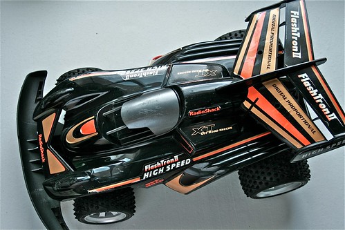
This afternoon I started stripping down the RC buggy I managed to buy for peanuts at the local car boot sale last week. My objective is to fit a new ESC, new Rx and motor if needed, and generally cleanup/improve the thing.
 |
| Radioshack Flashtron II |
 |
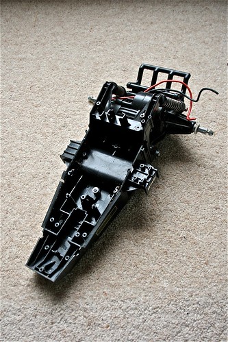
| Three screws later, and sans-shell. |
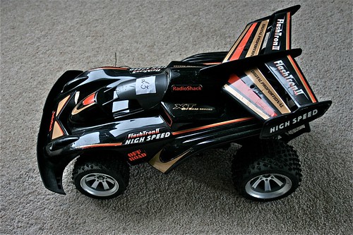
It was surprisingly easy to break down, as most is held together with screws, with some hinge pins in places (explained later on). The wheels use regular lock nuts to hold them in place, so a metric pit tool was all that I needed for them. Quite often I've seen wheels compression fitted, crimped or even held on with grub screws. It was refreshing to see keyed axles too - it opens up the potential future uses for the buggy and makes it easier to service and rebuild.
 |
| Ready to start stripping down... |
Taking the electronics cover off, I was shocked at the gunky mess inside. A combination of sand and gel the PCB has been coated in, has resulted in a complete mess. The buggy is incredibly clean on the outside, so I really wasn't expecting this, but since the old electronics are going, it's no real concern for me - just a bit of extra work cleaning it up (ie a soapy bath for it).
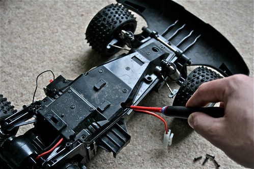 |
| The main bathtub and electronics bay protected by a single cover. |
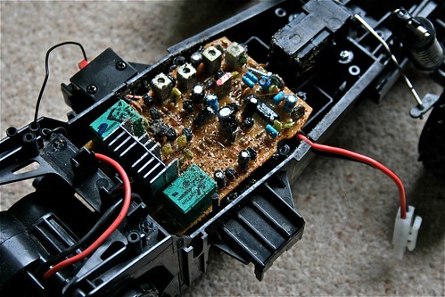 |
| Sand and gunk (probably seawater in the mix too) ≠ happy electronics. |
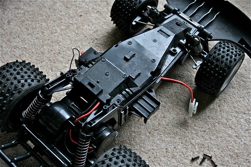
The electronics bay is packed solid with the old controller, so it will be straight forward fitting a 2.4Ghz Rx and a Tamiya 101 model ESC. There are plenty of air vents (enough for the bay to have been filled with sand in the past), so no real worries of overheating, and there are existing cable entry points, so no hacking required.
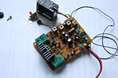 |
| Easily replaceable; the original electronics and servo. |
The motor has been soldered directly to the main board, along with the battery cable. The latter I'll chop off and keep, as those connectors are expensive (unnecessarily so). The motor will need a suitable connector for the new ESC - I'm not sure whether to fit something industrial, or just hack a solution. Failing that, I might just use a stock Tamiya motor, and do away with worrying about it.
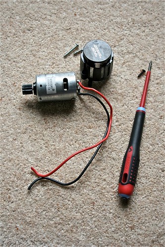 |
| Stock Radioshack 540 motor. |
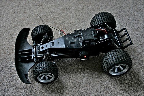
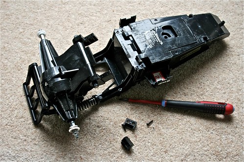
The old servo will also be going, replaced with a stock Acoms servo, and some spare Tamiya servo collars/horns. Rather bizarrely, the buggy features a standard servo mount with standard server horns - no custom plastic or weird case-less servos you normally find in RTR vehicles. It's a deep servo, so I may need to pack out the replacement servo (or completely bypass the mount, and do things differently). It'll probably need something higher-torque, but for now it'll do - first things first, I just want this to run on new electronics.
 |
| Bathtub chassis with rear-end, sans-everything else. |
I tried to open the gearbox, but found the rear-end is connected by a pin with caps that appear to be expansion fitted - so will require the pin to be cut to open the gearbox housing. I won't bother for now, unless the gearbox plays up badly, as I would need to replace the pin with something similarly tight fitting either bolted in place, or held by circlips.
 |
| It can be stripped further, but the hinge pin makes it pointless to do so. |
The front end came off easily, and since the suspension is also held together with similar pins, I'm not going to bother breaking down any more - just clean up and grease what I can. The bathtub chassis is nice and robust, and not cracked or damaged - there are plenty of scratches on the bottom, and on the bumper, but frankly there'll be more there soon :)
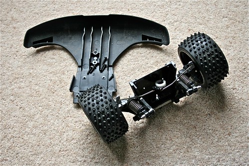 |
| Front-end with servo horn. |
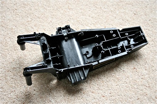 |
| The final stripped bathtub, ready for a wash. |
All-in-all, this looks to be in good running order, and with the upgraded electronics will be a nice little buggy to play with. In Part 2, I'll cover the reassembly, with some pictures of it running.
Finally, I'll leave you with the battery cover (well, a really clever clamp mechanism for holding a regular Ni-Cd/Ni-Mh 7.2V pack in place), sporting it's Radioshack part number.
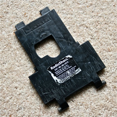 |
| Radioshack Flashtron II 60-4215 |
Subscribe to:
Posts (Atom)