Saturday 5 November 2011

Train Cab Control System Part 2

I've written and rewritten this post countless times as I've played around with the design and as parts have arrived. It probably makes little sense, but at least you get an idea as to where things are going...

Main Controls

I've gotten most of the push buttons and physical controls, and have devised numerous solutions for the main quadrant controls now.

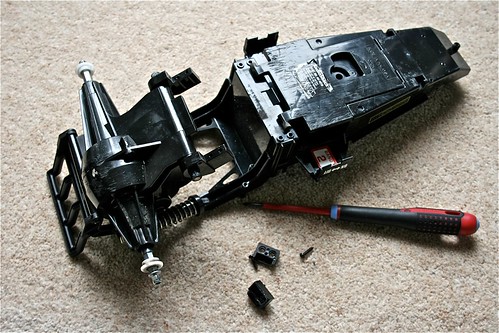
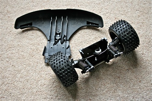
The first solution I devised, is to take some Telemec' joysticks, and rip them apart, building a custom aluminium framework to house them, and attaching a suitable mechanism to actuate a potentiometer. The second, is to not bother with quadrant controls...

As I've found, there are virtually no manufactures of them around, and those I've found are ludicrously expensive (or are an import job). In the end, the controls I thought would be the hardest to source (rotary hand wheels/levers) are actually proving to be the more easier.

So, for this first version, the brake will be a hand wheel with knob, and the throttle will be a rotary lever. I'm still awaiting the lever, but have already snagged a couple of the hand wheels. No picture at the moment, but will add one later.


Enclosure

The new enclosure arrived - I'm somewhat limited to space and initially to the kind of enclosure, so for the first panel, I'm tied to the dimensions based upon the largest pre-manufactured enclosure I could find.
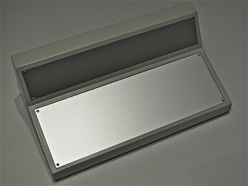
Boss Enclosure
Boss Enclosure
The enclosure consists of two panels - a main aluminium plate, where all of the controls will go, and a top aluminium plate, where the feedback and a couple of additional controls will go. The rear of the enclosure will sport a couple of connectors for power and data.

The enclosure should be deep enough for most of the components - where possible I'll tier/stack the Arduino boards on the back of some of the interface elements, and the others will be placed at the rear/back (the deepest part). Some of the Telemecanique controls are deep, so I'll have to cheat with positioning if I hit problems.

The layout of both panels will be done in CAD; I'll outline each component, and include it's cut-out, allowing me to shuffle around. I'll digitally precision cut a prototype panel out of card in our engineering lab, so I'll have something I can mount the controls to, and sit into the enclosure to check it works, and feels right.

Once I'm satisfied, I'll use an accurate overlay to mark the aluminium and to cut it. I don't have access to a laser or CNC cutter so I'll have to do it carefully with a bench drill - most of it is circular so no big issues. For square cuts, I'll have to ensure that the control has a bezel that will hide any imperfections.

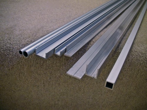
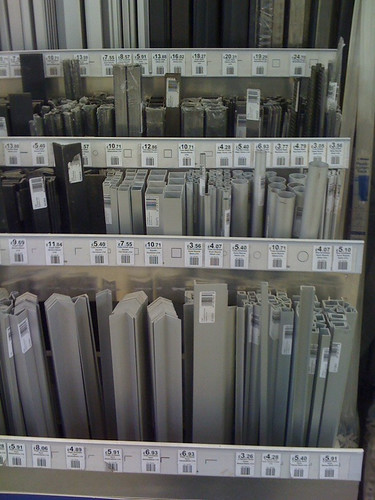
I've got a large stock of anodised aluminium extruded profiles, so I can easily build up and build down for some of the controls - perhaps making some look modular or segregated. Anything I make will bolt together - I'll rivet if needed, and I'll avoid welding the aluminium if at all possible.

Even though the enclosure is a beautiful shade of fresh-vomit-beige, I'll hopefully be spraying it to a bluish-grey that's common for modern train cabs - I'll need to play around with shades to get it right, and I'll avoid two-toning the plastic case. The aluminium probably needs painting as well, again that'll be a nice bluish-grey, though I may make it a dark grey for better contrast with the labels and pilot lamps.

All of the legends and labelling will be printed/precision-cut polyester, with a polycarbonate laminate - it's what's used on control panels, and should look great. Not sure whether to completely cover the aluminium, or just do it around each control. The CAD will help immensely in getting the artwork accurately shaped and cut.


Controls

As mentioned in the previous post, there's going to be a bit of work involved in integrating the panel with a DCC system. It's not going to be quite as easy as focusing on controls first and then programming afterward - I'll need to know how the programming will work, in order to figure how the controls can be implemented (and which are needed or should be avoided).

I would hope/expect at the least to have the following controls:
  • Throttle
  • Brake (with simulated deceleration/proportional braking)
  • Emergency Brake (emergency stop controls, bypassing the deceleration configuration)
  • Direction (forward/off/reverse)
  • Horn A (high tone)
  • Horn B (low tone)
On top of those controls the following could be included:
  • Parking Brake (on/off with pilot indicator)
  • Pantograph (up/down with pilot indicator)
With it being a DCC controller, there's a lot of benefits in having a full compliment of controls that can be mapped to the function keys, and have them labelled in accordance to what they normally are (and coloured/laid out appropriately). Then again, there's finite space, so some will be tactile, and others will have to be soft-controls, and accessed through JMRI or a DCC-orientated keypad (like a PS/2 keypad etc).

Telemecanique Joystick & Keyswitch
Telemec' Joystick & Rotary Key Switch
Telemecanique Stop Button
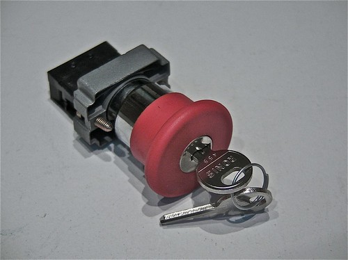
Telemec' Mushroom Key Button
Telemecanique Push Button
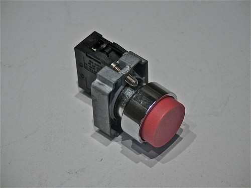
Telemec' Push Button

Information Panel & Feedback

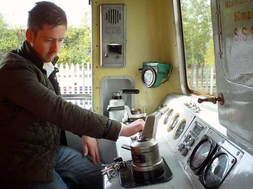
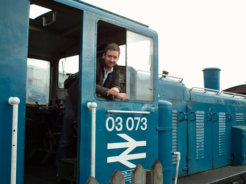
Part of the panel is to control a train, and part is to control the DCC functionality (such as consisting, selecting a train etc). Looking at modern train cabs, many feature glass-panel displays for diagnostics, train overviews (i.e. showing the rolling stock, consisting etc) and schedule information. In our case, we have JMRI, which will be offering a big chunk of this information - and in the same way as the real systems will need to have some form of tactile interface (touch screen or keypad), we'll need the same.

I don't want the DCC aspect to be obvious - it's whether I include a tactile interface on the panel, use a touch screen or rely upon an external keypad. Whichever, I need info from JMRI, and I need info for the DCC controller. And I need to control them both.

There's quite a bit of feedback for the panel to display - indicators, LCD's and needle gauges. I'm inclined to avoid needle gauges, and use multi-line LCD displays in their place.

The indicators could include:
  • AWS
  • Alarm
  • Overload/Trip
With displays/guages including:
  • DCC Config
  • Speed
  • JMRI Info
Naturally there are quite a number of input controls and output indicators I could include, but it really comes down to how realistic the panel is to be, and whether it's worth including them for the sake of doing so.

Telemecanique Amber Pilot Lamp
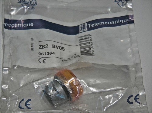
Telemec' Amber Pilot Lamp (sans-bulb holder)
Telemecanique Red Pilot Lamp
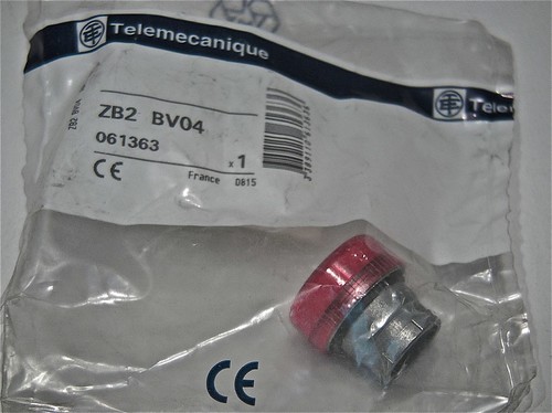
Telemec' Red Pilot Lamp (sans-bulb holder)

Programming & Function Mapping

An important part of designing the panel, is ensuring there are enough input controls to cover the most important functions, and mapping them correctly. This requires a bit of deep research, figuring out what standards there are, what I can actually control and how they're controlled. Simply, if a horn is generally a specific Fx number, then I need to know which it is, so I can map it to the correct button, conversely some functionality that should be on the control panel might not be controllable - it might need to be programmed instead or is hardwired, such as lighting etc.

As it seems that I'm headed towards an information display as part of the overall panel, then most of the functionality will be mapped out in a GUI form (mimicking a real-life HMI) - this should also serve as a means to select trains and interact with the LCB as needed.

Bigger decisions are with the underlying electronics and interfacing. I've spent a good few weeks researching the electronics, both prototype and scale, my conclusions of which are far too long for this post, so I'll ramble along on that subject later. I've got quite a few design considerations to make, and to decide on the buses and technologies that I'll build the panel and future layouts upon.

Resources

My first port of call will be MERG, the Model Electronic Railway Group, a membership-based society in the UK that focuses solely on the electronics aspect of model trains - there's some really interesting projects I'll probably cover in the future, including position locations using RFID and servo point control.

A great resource is OpenDCC, a German-based OpenSource project, that consists of hardware and software - including great guidance on implementing and programming DCC. The English translations are a little ropey in places, or missing altogether, but nonetheless this is the best resource I've seen (and seems to have the best technical understanding).

The JMRI project is of course an excellent source of information, though a quick Google search turns up some great blogs and presentations on JMRI.

Another great project that I recently found, Rocrail, offers an attractive alternative to JMRI, and something worth looking at.

Another useful resource is the NMRA, the National Model Rail Association - though US based, is pretty much the norm for most model rail standards, so will be reference for any integration with DCC.

Next Steps...

As you can see, I'm still trying to figure things out, and am planning/designing on the fly. I started writing this post weeks ago, re-writing every time something new came up, or a problem was solved, or a new problem was found. I'm getting closer, I think...

Wednesday 26 October 2011

Train Cab Control System Part 1

In the effort to occupy more of my spare time, and to create a problem to be solved, I decided that a regular DCC controller for my forthcoming OO layout is just not good enough.

Looking around, I've not found anything good enough or cheap enough to use, nor anything that's actually good-looking or remotely fun to use. So new projects, here we come.

The Idea

The idea is to build a pseudo-realistic control panel, that mimics the pre-requisite controls, and the type of touch and feel found in the cab of a real train. Because I don't have a specific train cab in mind, I'm not replicating a prototype panel in existence, but taking the essence of the feel of the cab and condensing that into something small enough to be used practically at home.

After seeing the InterCity APT a few weeks back, I've been inspired by the simplicity and general layout of it's controls. Coupled with images scouted from Flickr and with Google, theres enough scope to do something that is original, yet quite obvious as to purpose.

The Look & Feel

I started researching and planning an older style panel, but gave up when I made little headway in sourcing real (actual used/new parts) or pseudo-real (stuff that vaguely looks like the real thing) levers and parts. It seemed I'd be forced to make replicas; either approximate in size, or scaled to fit, using vac-form plastic and wooden parts. While relatively straight forward for me, I just don't have the time or space to be doing that at the moment (though I'm really keen to build a mini-vac former so I can do it in the kitchen).

Having stared at the pictures of the APT cab, it dawned on me that not only can I build a modern cab using actual components (allowing me to get away from the "hand-made" look), but I'd have enough wiggle room to build something that could look like a prototype off Bombardier or Siemens' next design.

By using the same kind of switches and selectors as would be used in an actual cab, the panel should have the same feel - even with clunk-click selector switches for direction, and large illuminators for feedback. I'm not planning to use electronics parts (the kind you pick up at Maplin), but the regular day-to-day heavy duty controls that we use in proper control panels.

The Controls & Electronics

The manufacturers of train control systems, for the most part, use these electrical components in their panels - there will however be some difficulty in sourcing the two quadrant levers used for speed and braking, and any needle gauges (yup, seems like they're still being used). My initial thoughts are to utilise LCD displays for speed, braking and "general information" (i.e. the DCC train selected and other programming stuff).

I'm also considering how advanced it should be, as a keypad might be useful - then again, with the palette of functions in DCC, provided I settle on function numbers for each function layout-wide, there'll be actual buttons for those functions - two-way horn buttons, light switches, pantograph controls etc. A ball-mouse or trackpad is probably overkill, but worth considering for JMRI integration.

It'll basically be a panel building job, tied into an Arduino based I/O card, and a couple of extra bits of electronics for the gauges. I'll also finish it with nice rugged connectors for power, data and USB (interfacing the Arduino).

For the most part, I'll used Telemecanique buttons and switches, though the quadrants might be a custom build using Telemec bits and bobs, and some scratch building for the framework. The LCD units will be of course interfaced with the Arduino, but are as close to what would be used, that they'll be fine. I'm not going to use little LEDs etc, but instead use actual pilot lights (big, but the real thing).

I've sourced a large angled console enclosure, that features a display panel - and excellent mimic of the real thing. Using aluminium, I'll build one or two brackets, one to hold a mini LCD display (for JMRI) and one to hold some additional controls I might implement in the future. I'd love a touchscreen, but I think it might knock the panel over using it, so that'll be a separate project (a signal operators panel I think).

It'll be tied together by a paint job to the case (greyish blue/bluish grey) and polycarbonate-coated polyester labels (again what's used in combination with traffolyte for the real thing).

I'll of course go balls-out on the internal cable looms, even though it'll spend most of it's time sealed. Might put thumb-screws on for easy internal access...

DCC Integration

The biggest issue that was always going to present itself, was integration with a DCC system. After spending time chatting with the folks at MERG, it seems that my original thoughts are correct, and that unless I plan to write an entire DCC stack (ermmm, no), then I need something else to do the DCC control.

So this leads onto JMRI and CAN-Bus.

I have two options at this stage, both involve JMRI as the core DCC control stack. The panel can either interface through customer code using USB and acting as an input to JMRI, or it can be part of a CAN-Bus network, and the CAN-Bus controller can interface JMRI. Thanks to the work at MERG, the latter looks to be the easiest.

More to come, plus I'll start posting pictures of parts as they arrive. Lots to think about on the code side, and integration, so again, more to come.

Stay tuned.

Monday 10 October 2011

Monkey-fun

In a packed weekend, I got to see lots and lots of Barbary Macaques up-close in a forest... Oh and I got to drive two trains.

Oh yes.

Not only did I get to drive a class 03 diesel shunter (03703), but I got to drive a class 73 electro-diesel locomotive tractor unit (73006) too... Both were in their BR colours; a wonderful combination of BR Blue and yellow (with the body in the distinctive BR greyish-blue and the cabs in the normal yellow).

DSC00038
Class 73 Electro-Diesel (73006)

I'm not sure which I loved the most, driving a 600hp generator on rails (the 73) or the 200hp farm tractor on rails (the 03). Both are so different, but both fantastic to drive; the former is what you'd expect from a train - ammeters, voltage regulators and a wide range of mode selectors, and the latter is a simple combination of air-selected gear changing and a throttle.

DSC00071
Class 03 Diesel (03073)

A short post, but I'm in the middle of getting the Arduino code right for the twin-thruster controls... Oh, and I've got plans for a few of new projects, including an OO (1:76) track inspection carriage (a real one, that'll use image analysis software) and a DCC control panel that mimics a real set of cab controls.

Lots of pictures to follow...

Thursday 6 October 2011

RIP Steve Jobs

I've never been one to idolise, nor one to have personal heroes, but to me, Steve Jobs has always been a hero and an inspiration since my first foray into Apple Computers, and it's colourful history. I love watching his keynotes (even after knowing what was launched or announced), they motivate and captivate like no other. His attention to detail and passion are present in every product. His vision and his compelling ability to excite and inspire will be sorely missed, but never forgotten.

Monday 19 September 2011

Hovercrafts & Models

Another car boot, another treasure trove of finds - including an RC hovercraft, sets of Star Wars model kits and a pristine Scalextric set... Awesome!

Like the RC boat, the hovercraft features twin props, that deliver forward/reverse/left/right, with a third channel controlling the inflation fan. I've already tested and promptly stripped down the hovercraft, with the aim to upgrade in a similar fashion as the RC boat, but also to fix some major design flaws.

IMG_3087
RC Hovercraft

The first flaw being the inflation fan's power dropping when the props are driven (the main motors just steal the power from the inflation motor), forcing it to deflate. The second is the gap between the inflation fan and the air intake - there's no ducting, so when the air pressure is high (i.e. when it inflates) the air is blown back along the internal shell of the body and blown out through the air intake.

Both of these flaws are fixable, the first resolved as a result of replacing all of the electronics I planned to do anyway in a mirror of the RC boat (putting in two batteries instead). There'll be one battery powering the inflation and the electronics, and one battery powering the twin props. The latter will use the same electronics design as the RC boat. I plan to use the third channel on the Tx/Rx to offer a latching control for the inflation - enabling the hovercraft to be powered on/off remotely.

The second problem requires a bit of hacking (that'll be made good with a complete body respray), and involves a piece of ducting being formed between the fan and the air intake. It needs to be lightweight and plastic - the bottom of a plastic disposable cup/pot springs to mind; the right shape, can have a hole in the bottom cut to line up with the fan and can be cut to height to fit the gap (which is considerable).

As hinted, I'll respray the entire body shell - I'm thinking in a military grey, accented with red and white safety stripes I'll cut out in vinyl.

I'll post the strip-down with photos in the next post, and I'll mention the Star Wars models in a little more depth later on as well...

Tuesday 30 August 2011

Arduino RC Boat Speed Controller Part 1

Prompted somewhat by coincidence, we happened upon a small model boat exhibition this bank holiday weekend, in the grounds of Holdenby House alongside it's food festival. I took plenty of pictures of the boats (and birds of prey in their falconry centre), but neglected to take pictures of the food - whoops...

Though I probably don't need to completely upgrade the electronics for the RC Boat I snagged a few months back, I've been getting carried away with designing cool solutions nonetheless. The boat uses two motors for both thrust and turning, with the current electronics taking both Rx outputs (throttle/steering) and converting them into two throttle output values.

To be honest, I've not actually opened up the boat's electronics compartment - I just had a look inside the main shell, and decided to replace the Rx to 2.4Ghz and in turn the ESC to something compatible. For all I know, it's a separate little packaged ESC that does exactly what I want, and doesn't need replacing, then again, it's probably just one board, with all the Rx and ESC electronics. Both motors are wired direct from the electronics compartment, along with the battery supply cable.

Just three screws, and I'll have my answers, but my solution is better than anything that's likely to be in there already (let's just pretend that's the case for now). I'll check tonight, I promise!

So let's just plough ahead full steam anyway.

The Problem: An electronic speed controller that can control twin motors, and based upon steering input, correct/shift the power between the two motors to produce the appropriate turning.

The Solution: Arduino!

I've seen this boat modified with an outboard rudder (with a very nice aluminium structure), and with the motors presumably "Y" linked to the ESC (or two ESC's with a Y-link to the Rx). That's Stage X in my mind, I'm just looking at this early stage (ermm, Stage 1) to put my mark on the boat, without too much hacking or expensive modification (minus the over-the-top solution to follow).

The solution I've decided for at this stage, is to replace both the Rx and ESC with a new Rx (2.4Ghz) and with a pair of brushed ESC (TBC), combined with an Arduino to process the signals from the Rx and to convert into proportional control of the two ESC. The Arduino can then also do other interesting stuff in the future, courtesy of a 3rd channel on the Rx.

Initially, I'll prototype the solution with servos instead of the ESC (they have the same interface, so shouldn't have any problems), as I don't have any spare motors or even any spare ESC at the moment (on order still). The input will be from the Rx, using some custom made cables, and hopefully everything will be powered from a single bus or perhaps two buses to balance the ESC outputs.

I'll start with a single battery powering both ESC, as I don't have much space at the moment for extra batteries (well, whilst this is on the workbench I do but long term I don't). I may have to move to lithium to increase the runtime.

The Arduino will interface using a servo board, with both outputs of the Rx and both inputs of the ESC sitting on the bank of servo I/O - so no wiring or hacking required. The power supply for the Rx and Arduino will come from the ESC's regulated output - as mentioned, still to decide as whether both will come off one, or one each from either.

I've already written a draft script, that just passes the throttle through to the motors. The next draft will introduce a basic proportional control - the R&D comes at this point, where I need to play with three approaches to the proportional mathematics.

In Part 2, I'll show the prototype in more detail (including circuitry), and cover the results of the R&D. Hopefully, in Part 3, I'll be able to show it being installed in the boat, and some tests of it in the water. Between now and then, I also hope to do a post on the boat, and it's strip down, and perhaps a wet test in it's current state.

Friday 29 July 2011

Notable Absence

This month has flown by; I really can't figure out why July has come and gone seemingly overnight. Admittedly, I've been incredibly busy; new projects, finishing old projects and a new routine.

I've still got a back log of projects that I've hinted at before - idiotically, it's not even down to me being busy, most of the parts I need have only just turned up. Still waiting for my new RC controller (seriously, it's three months late) plus some other rogue bits I ordered a month back.

Anyway, I've got some exciting news regarding a new project (well, two projects, one high-tech, and one creative). More about that later...

Anyway, I promise to keep up with regular posts!

Saturday 25 June 2011

Vinyl Crazy

Over the last few weeks, I've become obsessed with vinyl, and screen-print artwork. My aim is to make vinyl artwork with the feel of screen printing, but the textures and durability of vinyl. Why hang a piece of art, when you can turn a wall or any surface you have into a work of art? (Rhetorical question, I'll have you find).

Anyhow, I've been screwing about in the studio with vinyl cutters and thermal presses, with the hopes of creating something great. I'm hoping to work with a couple of awesome illustrators to produce some unique pieces of artwork, so stay tuned for more info.

In the meanwhile, if you're interested in my vinyl services, including; cutting (vinyl, metallic films, stencil film etc) and thermal printing, then get in touch with me: jon(at) followed by shotbymccoy.com. We can cut, mark and print most materials, so if in doubt, feel free to ask!

I'm trying to figure a way of combining my photography with my vinyl, to create a bastardised format... I have some crazy ideas in mind, I'll endeavour to post some as I get shooting.

Ta-tah for now...

Saturday 11 June 2011

RC Buggy Project Part 2

Having been watching the F1 trials in Canada for most of the day (interspersed with watching Japanese new channel NHK), I'm lusting after a glistening workshop, complete with gloss white tool cabinets, gloss white workspaces and a torque wrench. I'm hoping my new lab-slash-studio will look as cool when it's finalised - it's got white walls, ceiling and a grey floor, so we're on the way!

Anyway, in this final part of the project, I'll be rebuilding the buggy with new electronics, and getting it ready for it's test drive.

I've been waiting for nearly a month now for some of the parts (in general, not just for this), and a good few weeks for others. I had to steal a few parts from an existing car (motor and speed controller), but that'll have replacement ones and a new Rx as soon as the parts arrive anyway.

I decided to save time and effort by using a stock Tamiya 27T motor, complete with bullet connectors and the Tamiya 101 ESC it was attached to, off of my Tamiya Enzo Ferrari... I've also used a new 2.4Ghz Rx instead, not just for reliability but for it's miniature size (they're a good 75% smaller than analogue Rx).

Inventory:
  • Motor: Tamiya 540 27T (any 540 approx 27T will do)
  • ESC: Tamiya TEU101-BK
  • Servo: Acoms AS17
  • Radio Tx: FlySky GT3B
  • Radio Rx: FlySky GR3C
IMG_2092
FlySky 2.4Ghz Receiver

IMG_2088
Stock Acoms Servo

The first step was to wash the parts, minus the gearbox, which got a good wipe down instead. I ended up submerging and washing the other parts (all plastic minus the front-end) which made it a lot easier to get the sand and gunge out.

IMG_2095
Clean parts ready for re-assembly.

Once dried and ready to re-assemble, I tried dry-fitting the electronics into the main bathtub as best I could, along with the servo. With the lid on, the servo fitted and with a bit of shuffling, the electronics did as well. Interestingly there was a slot perfectly in line with the top flange of the servo (with a recess and raised guides for the bottom flange) and even a space for the servo cable.

IMG_2119
Dry-fitting components.

Once everything was in place (with cable ties), I tackled the servo mount, which ended up being a saddle by virtue of using long enough screws and allowing the bracket to bend over the servo a little. There's a little pressure from the bracket against the top lid, but nothing significant. Long term, it may be better to carve a chunk of the plastic from the top of the servo slot to give the bracket some clearance, but for now it'll run perfectly without doing so.


IMG_2129
Cable tied and neatly organised.

The servo sits without any movement and moves freely without obstruction, so all in all the servo replacement has been straightforward. I couldn't use the original servo horn, given the tooth shape, but having to only replace one component has to be pretty good!

IMG_2131
Servo mounted with original servo saddle.

In rebuilding the back-end, I used the original push-on pinion gear and the Tamiya 27T motor stolen from my Ferrari. There wasn't much to do with the back-end, apart from routing the cables (which will be zip tied to the upper suspension arm), and reattaching to the main bathtub chassis.

IMG_2144
Back-end with new Tamiya 27T motor.

IMG_2146
Assembled and ready to go, sans-shell...

IMG_2153
Ready to go...

I test drove the buggy in the driveway, and all seems good. Took a hell of a lot of trimming to get the steering and throttle correctly balanced - the steering servo needed reversing as well. I'm enjoying the FlySky controller, I like the setup and the ability to tweak all of the settings whilst the vehicle is moving. Though still getting used to the controls, and the "End" button being the "Enter" button, and the "Enter" button being the "Select" button.

When Ms R. is back, we'll take the buggy to the park, and film it in action. Until then, I'll start getting to grips with the chassis design for the new truck.

Thursday 9 June 2011

The RC Truck Part 1: Design and Parts

In lieu of a decent name at present for the rock-crawler slash 4x4 slash thing with wheels, I'm going to call it the "Truck".

I can see this turning into a long series of posts, to get enough detail and ramblings in for the whole design and construction process.

In this first post, I'll cover most of the design logic, and a lot of the parts being used. By no means will this be a finalized design prior assembly, nor a parts inventory, but should give others dumb enough to want to build an RC vehicle like this, sufficient pointers to get something under way.

Chassis

The design for the chassis is where the whole idea came from - to build a basic structure using aluminium extruded profiles and with conventional fixtures and fittings.

I've got a lot of ideas for chassis, and given how much aluminium I've got, I'll probably try a few (I may even consider using quick-release hardware to enable the axles to be moved between chassis). Dictated by the axles, the scale and general structure will be built to accommodate the positioning of the suspension and linkage mount points. As the battery and electronics are discrete enough to be fitted anywhere there's space; the axles are the most critical thing to secure before construction.

I may consider a payload on the vehicle, so it may be necessary to tweak the design accordingly, to create a bit of useful space. I'm thinking mainly electronics so not a massive weight.

Axles & Drive Trains

I can see only two ways of approaching a project like this - hack or buy existing axles. Falling short of designing a gear box, axles and housing, I thing the best solution is to either hack existing drive train components or to buy whole drive trains. The former still leaves a lot of issues, as to building a housing and getting the steering, diffs, axles and gearboxes mashed together. The latter is a lot easier, as you can either rip the units of existing used vehicles (eBay etc), or buy the drive trains as spares. The trouble comes in ensuring the chassis is somewhat similar in proportions to the original vehicles, at least in terms of linking the suspension and the four pairs of linkages.

From an early stage I opted for Motor-on-Axle rather than using a drive shaft to a centrally mounted gearbox, for a start it makes each drive train a single unit that just needs power, it increases the range of motion, lowers the centre of gravity and reduces the number of moving parts liable to screw up.

I couldn't find anything used in the time frame I set myself, so I sourced a pair of Gmade drive trains (sans-motor, pinion gear and servo). The beauty of these is that they're reversible, allowing for a simpler mirrored chassis design and also allowing for front and rear steering.

The drive trains do have diffs, and from what I understand, they're not lockable on this, falling short of gluing the diff, or filling with diff lock grease. Can't have everything.

Suspension & Linkages

This area is giving me the most grief.

Hardware wise, I think I'll source either spare parts from HPI or Axial cars, or try to source anodized aluminium hex nuts/bolts - not an easy task either way.

I've sourced Ansmann 95mm shocks for front and back, and I'm on the lookout for linkages. I'm planning to use two pairs of links for each axle; forming a "W" shape. The suspension will be almost vertical so there'll be plenty of movement and sufficient rigidity.

Edit #1: I've sourced a set of Axial XR-10 linkages and chassis mounts, so hopefully it'll all come together.

Edit #2: Having now received the axles, it looks like my search for linkages was in vein, as they've got a complete set with them, plus lots of extra bits as well. And a really dumb error, I assumed the XR-10 was 1/8th scale for some reason, but it's 1/10th. The linkages should be okay though, as the they have the right mechanical specs - though I might not need them if the Gmade ones are good enough.

Motors & Electronics

As mentioned, both axles will be powered by 35 turn HPI Saturn motors. They're quite general purpose, so it'll have a bit more speed than regular rock crawlers, with a loss in capability on the rockier terrain. They're easy to replace at any time, so I can always put 55 turn for some heavy rock crawling.

I'll be using another 3-channel 2.4Ghz Rx, so I'll have an extra channel to play with (perhaps to enable/disable rear steering etc). For cost and simplicity I'll start with a single Tamiya ESC (104), Y-linked to the motors, allowing for parallel control of both motors. I may find that a bad solution, especially if one axle gets jammed, and the other motor gets fried - but I'll need to play around with the safety and overloads of the ESC, and just be careful in general.

The front axle will have steering, with option of unlocking the rear and putting steering on that too. I might gear down the servo on the rear to reduce the steering effect, that I'm not sure of at present. Initially I'll build with a stock Acoms servo, but I will install higher-torque ones as needed - I can see this being an issue very quickly.

Wheels & Tyres

I've luckily managed to source a set of Axial SCX-10 rims and tyres, so all should be sorted on that front. That makes for a nice short section.

Body Shell

I'm undecided what I want it to look like... It can go any direction at this stage! I do like the look of the Axial XR-10, so I might take that approach, at the same time a Land Rover 110 would be cool. And also making it look like a military robot has it's charms too (think carbon fibre looking, works well with all of the aluminium). I'll sketch a few ideas out, and see where it takes me.

With the 1/8th axle scale, it's going to be a little harder to find a suitable shell, without this looking like a monster truck (not a bad thing, but not the intention). I'm also inclined to fit a lot of surveillance equipment, so a more ruggedized shell will probably be called upon! I'm probably going to rename it something pointless, like the "All Terrain Surveillance Drone" or ATSD if that's the case.

For now, I think that rounds of most of the "design", and explains most of the parts I'm using and the reasoning behind it. In the next few parts, I'll cover the build-out of each component and some interesting little tidbits along the way too.

I'm off to start cutting aluminium and bolting crap together.

Wednesday 1 June 2011

RC Buggy Project Part 1

I've managed to source more parts now for the RC projects, including:
  • Set of 4x Ansmann 95mm Shocks
  • A pair of HPI Saturn 35T Motor
  • An HPI Firebolt 15T Motor
  • Lots of Tamiya ESC (104 model) - for existing and new vehicles
I'm now just short of linkages/suspension arms for the truck, which I'm not finding easy at best. Think I might have to machine them, or find something I can re-engineer...

This afternoon I started stripping down the RC buggy I managed to buy for peanuts at the local car boot sale last week. My objective is to fit a new ESC, new Rx and motor if needed, and generally cleanup/improve the thing.

IMG_2001
Radioshack Flashtron II

IMG_2004
Three screws later, and sans-shell.

It was surprisingly easy to break down, as most is held together with screws, with some hinge pins in places (explained later on). The wheels use regular lock nuts to hold them in place, so a metric pit tool was all that I needed for them. Quite often I've seen wheels compression fitted, crimped or even held on with grub screws. It was refreshing to see keyed axles too - it opens up the potential future uses for the buggy and makes it easier to service and rebuild.

IMG_2010
Ready to start stripping down...

Taking the electronics cover off, I was shocked at the gunky mess inside. A combination of sand and gel the PCB has been coated in, has resulted in a complete mess. The buggy is incredibly clean on the outside, so I really wasn't expecting this, but since the old electronics are going, it's no real concern for me - just a bit of extra work cleaning it up (ie a soapy bath for it).

IMG_2012
The main bathtub and electronics bay protected by a single cover.

IMG_2016
Sand and gunk (probably seawater in the mix too) ≠ happy electronics.

The electronics bay is packed solid with the old controller, so it will be straight forward fitting a 2.4Ghz Rx and a Tamiya 101 model ESC. There are plenty of air vents (enough for the bay to have been filled with sand in the past), so no real worries of overheating, and there are existing cable entry points, so no hacking required.

IMG_2027
Easily replaceable; the original electronics and servo.

The motor has been soldered directly to the main board, along with the battery cable. The latter I'll chop off and keep, as those connectors are expensive (unnecessarily so). The motor will need a suitable connector for the new ESC - I'm not sure whether to fit something industrial, or just hack a solution. Failing that, I might just use a stock Tamiya motor, and do away with worrying about it.

IMG_2038
Stock Radioshack 540 motor.

The old servo will also be going, replaced with a stock Acoms servo, and some spare Tamiya servo collars/horns. Rather bizarrely, the buggy features a standard servo mount with standard server horns - no custom plastic or weird case-less servos you normally find in RTR vehicles. It's a deep servo, so I may need to pack out the replacement servo (or completely bypass the mount, and do things differently). It'll probably need something higher-torque, but for now it'll do - first things first, I just want this to run on new electronics.

IMG_2033
Bathtub chassis with rear-end, sans-everything else.

I tried to open the gearbox, but found the rear-end is connected by a pin with caps that appear to be expansion fitted - so will require the pin to be cut to open the gearbox housing. I won't bother for now, unless the gearbox plays up badly, as I would need to replace the pin with something similarly tight fitting either bolted in place, or held by circlips.

IMG_2040
It can be stripped further, but the hinge pin makes it pointless to do so.

The front end came off easily, and since the suspension is also held together with similar pins, I'm not going to bother breaking down any more - just clean up and grease what I can. The bathtub chassis is nice and robust, and not cracked or damaged - there are plenty of scratches on the bottom, and on the bumper, but frankly there'll be more there soon :)

IMG_2031
Front-end with servo horn.

IMG_2045
The final stripped bathtub, ready for a wash.

All-in-all, this looks to be in good running order, and with the upgraded electronics will be a nice little buggy to play with. In Part 2, I'll cover the reassembly, with some pictures of it running.

Finally, I'll leave you with the battery cover (well, a really clever clamp mechanism for holding a regular Ni-Cd/Ni-Mh 7.2V pack in place), sporting it's Radioshack part number.

IMG_2047
Radioshack Flashtron II 60-4215

Friday 27 May 2011

RC Bits

Things are hotting up a little more on the project front.

Okay, that massively oversells the projects more than is most likely due. But nonetheless, I've got some bits on order, and hopefully will start seeing them arrive next week. The bits include:
  • FlySky FS-GT3B (2.4Ghz transmitter/receiver)
  • Gmade Spider Axles (1:8 scale motor-on-axle rock crawler axles)
  • 2xPair of Drifting Tyres (for 1:10 Tamiya)
What I need to source now, is a couple of ESCs (for the boat, buggy and scratch built truck), 540 motors, some additional receivers and some higher capacity batteries (and matching chargers). Might need some high-torque servos as well for the new truck...

Random musings over. Resuming normal transmission.

Wednesday 25 May 2011

Aluminium!!

After a quick supplies trip this evening, I've stocked up on some extruded aluminium profiles for projects and general fabrication. Won't go so far as to list them, but as I publish projects I'll include the component specifications and a couple of suppliers for each.

Aluminium!!
Extruded aluminium profiles.


The first set of projects on the books is the rebuild of the two new RC vehicles, followed closely with the scratch-build of an RC rock crawler and/or surveilance vehicle using some of the lovely aluminium above.

The second set of projects is looking to be based around building a set of sensor arrays for around the house, using Arduino and a range of modules, including ZigBee for wireless communications.

After these, or during these, I'll be revisiting the Armatron and getting an Arduino to control it. I started having second thoughts about it, having seen what fantastic condition it's in, and how cool it really is, so I'll be quite conservative in my approach to hacking it.

Finally, if I get enough time to do all these things, then I'll try and setup a supply outpost for people who want to get hold of any of the obscure things I use and source for my projects...

I'm off to work on Ms R's business cards.

Tuesday 24 May 2011

RC Fun

Two weeks of car boot sales (I do love them) have resulted in a multitude of treasures (see life-long debate of "one man's crap vs other man's treasure")...

In homage to the generation game:
  • one vintage Polaroid camera (complete with old film cartridge)
  • a radio control speed boat (boxed with controller, charger and battery)
  • a radio control buggy (sans controller or battery)
  • a set of collectable Star Wars prints
  • a plastic airplane model kit (unpainted)
Ms R. purchased even more crap than I did (crap, treasure, blah, blah) and yet managed to spend virtually nothing. Volumetrically it's a lot less than mine. To the point that my crap is pretty much in the way of everything. Anywho, I'm digressing.

The plan is to rebuild both; upgrading the receivers, speed controllers and motors, and just generally improving the way they work. The boat looks pristine, but has really cheap radio gear, motors and propellers. The buggy looks a bit dusty, but sound, with normal consumer radio gear and motor.

The boat has twin motor drives, and uses offset control of the motors for left/right - which is nice, but means finding a speed controller is virtually impossible (for a small budget at least).

The buggy has motor-on-axle rear-wheel drive and good suspension, it's an easy project, given that there's enough space to mount new electronics and to get it up and running with only a few hours work. I have new radio gear on order, so hopefully will have it soon to begin these upgrades.

The next project I think is to scratch build an all terrain vehicle from aluminum profile, using the plentiful supply of parts found on eBay for the drive train and moving sub-systems. Still undecided as to whether it'll be a surveillance style (tracks and flippable body) or rock-crawler style.

Stay tuned...

Saturday 14 May 2011

Japanese Stainless Steel

We popped into our local kitchen shop this morning to buy Ms. R a cat apron (or rather, an apron with cats on it, not an apron for cats), and ended up spending far too much on some really high-quality utensils.

First a ludicrously heavy griddle pan, perfect for tonight's steak and vegetables...

Second, and my personal favourite, is a Global Japanese-made stainless steel "oriental-style" pairing knife, and a diamond sharpener for our other knives.

Global 25th Anniversary Oriental Knife

I love tools, and believe in buying good, high-quality and durable ones - made by the best manufacturers I can afford to buy. I see knives as being no different; they should be made to last a lifetime and with the right care they can.

So I've been trying to find a good set of knives for years; and never found anything I actually wanted to invest in, until I spotted some ceramic knives a few months back. Having only just washed one of the ceramic blades, it chipped placing it wet on the draining rack - not something I would expect of a supposedly high-grade blades (turned out they where made in China, though branded by a high-end traditional manufacturer). I took them all back, and gave up looking, with the intent of investing serious money some other time into proper Japanese knives.

I spotted some well priced ceramic blades this morning, and was weighing up buying one to try, as again, they where made by a high-end manufacturer, or whether to plump for steel. Checked the small print - low and behold made in China. Decision made for me. I narrowed my choice down to Rockingham layered blades and Global Japanese steel blades. While the Rockingham seem to have perhaps the best finish now, I was a little put off by the handle construction - the Global knives are all one-piece with sand-filled handles, so have really nice balance and weight.

I've started with a pairing knife, as these I find tend to give you the biggest range for most preparation work - the oriental model feels much nicer than the normal vegetable models, plus I think it'll be a good knife for sashimi, so I've decided to start my new set with one of those (a GS-58 to be precise). I was eying up a couple of choppers, but since they start from £110, I think I'll be waiting a little for those. In the meanwhile, I'll keep our existing knives sharp with our new Global sharpener (tempted by the wet stones for a better finish in the future), and make do with my current chopper-come-mini-clever.

I've been sharpening and slicing bits of apple for the last couple of hours.. Need to hide the evidence I think :)

Though we'll probably have great local steak this evening,  I can't wait to start cutting things with my new knife!

Tuesday 26 April 2011

Nice Rack ;-)

Aluminium in all shapes and sizes...
Aluminium Loveliness...
Spotted this lovely rack of Aluminium (and cold rolled steel) profiles in a local DIY store the other day (Wickes), and trying to figure out how many fun things I can make with this stuff. Way to expensive, but it's nice to see a such a specialist range of profiles so readily available. If I'm caught in a squeeze I'll know where to go, but for everything else I think I'll be buying trade!

Keepin' on top of me...

One day I'll find the time to work on a new site to host each blog in it's own little fluffy cocoon, but until then checkout the latest posts from the other blogs on the left hand tool bar.

Saturday 5 March 2011

Clouds

It's time to be a little mysterious...

We're working on a brand new project; well two really, but both leading to a really cool new set of products. Can't say much about them, other than them being a fraction of the cost of the big industry player's products, and being accessible to pretty much anyone.

I'll let the title be a clue... When the project starts getting a little more vocal, we'll be posting lots to the project's blog.

On a side note, can't wait until September, and the new fibre being pulled in! Whoot!

Wednesday 2 March 2011

Makezine

If getting the latest issue of Wired through the post yesterday wasn't the highlight of the week, then getting the latest issue of Make definitely is!

A couple of fun bits and pieces I sniped on eBay have been turning up too, so it's probably time I actually start writing up a few projects, taking pictures and filming things breaking...

Wireless Sensor Networks and Safety

Not quite the sexiest of topics, but an interesting one nonetheless. My work finds me at current designing and architecting conventional albeit highly reliable and fail-safe (literal failure of anything results in electrical and physical isolation/safety states) cabled systems. A combination of both electrical and pneumatic actuation, coupled with two and three wire sensors.

A feature of all these systems, as hinted at, is the necessity of safe failing design. To ensure that the failure of a sensor, cable, relay, contactor or controller results in a safety state, rather than a potentially lethal state. A prime example, is to energise-to-run, and close-to-permit. Translating this to wireless sensors and actuators proves a little more challenging.

My underlying concern is always with a software failure within the wireless stack or within the gateway controller. With most wireless being ZigBee based, at some point a software stack that's less than bullet-proof will be involved with processing the data.

Yes, everything has a mode of failure. It's a given. But some things have significantly high numbers of modes of failure. Anything with code is a prime example of the latter. So, rule one would be to reduce the criticality of the modes of failure - prepare for the worst, so ensure the modes of failure give you an appropriate feedback, rather than false feedback.

I'll expand more on safe design a little later, but this really just scratches the surface and introduces Wireless I/O for some interesting projects to come...

Tuesday 1 March 2011

New Month, New Style

Well, it's March already, and so to make up for a distinct lack of chat, a new styling will make do. Both "Shot by" and "Made by" receive the new design, with newcomer "Loved by McCoy" to follow with a lighter version of the theme. To begin, the only distinction between the sites will be their backgrounds, but I'm sure they'll be tweaked adequately in time.

Anyhow, back to work.